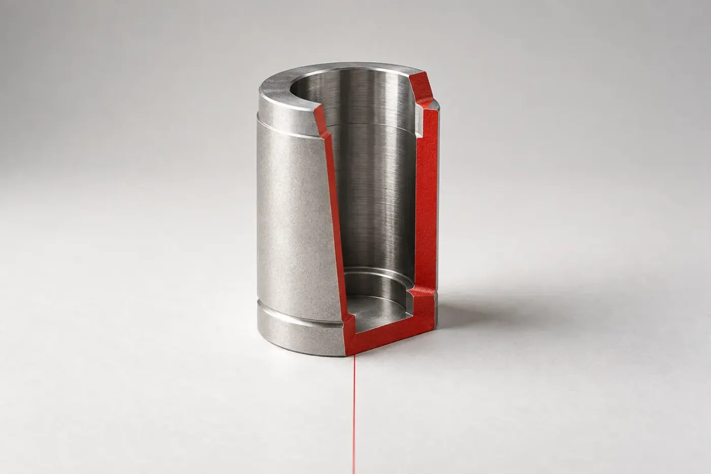
In a SOLIDWORKS drawing, use Insert > Drawing View > Section, place a cutting line on a parent view, then place the section on the sheet. To inspect a part or assembly on screen, use View > Display > Section View instead. The drawing route creates a view with a cutting line and label; the model route changes the display without adding a cut feature.
For a bore that must stay visible after a design change, I'd tie the cutting line to its centre. That reference lets the line follow the hole when its position changes, so the section continues to show the feature the drawing needs.
Make a section view on the drawing sheet
Start with a drawing containing the parent view: the view through which the cutting line will pass. If you still need the sheet and first view, begin with making a drawing from the model. The following commands use SOLIDWORKS Design 2026.
- Click Section View on the Drawing toolbar, or Insert > Drawing View > Section.
- In the Section View PropertyManager, open Section. Under Cutting Line, select Auto-start section view for a straight cut.
- Choose Vertical or Horizontal. Move the line through the feature you need to expose, then click to place it on the parent view.
- If an assembly or rib feature brings up the Section View dialog, set the exclusions described below.
- Move the preview clear of the parent view and click to place the section. Check the viewing direction, matching letters and hatched material.
If the preview lacks the model contents while you drag it, enable Show contents while dragging drawing view under Tools > Options > System Options > Drawings. This controls the moving preview; it doesn't define the cutting line.
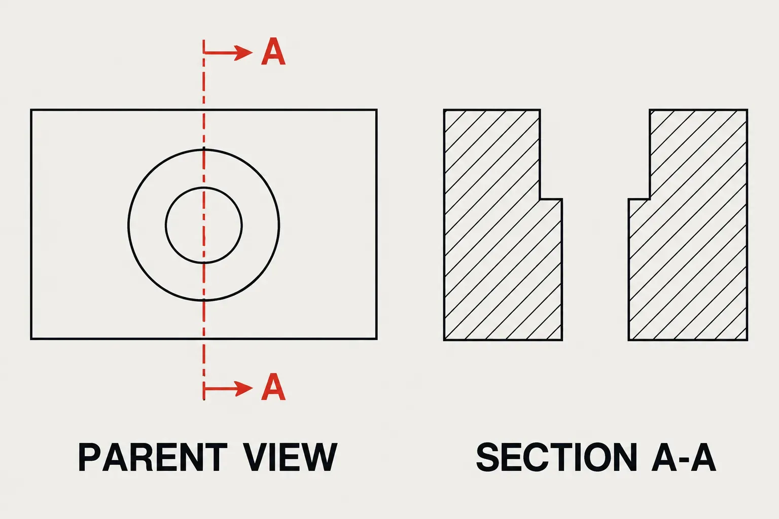
Choose the line that reaches the features
The Section View creation controls provide these routes within the same tool:
| Needed cut | Control and placement |
|---|---|
| Straight vertical or horizontal | Choose Vertical or Horizontal, locate the line, then place the view. |
| Straight at an angle | Choose Auxiliary, locate the line and set its angle before placing the view. |
| Two segments meeting at an angle | Choose Aligned, place the vertex, set the first segment's angle, then the second, and place the view. |
| A stepped cut through separated features | Clear Auto-start section view so you can add offsets before placing the view. |
| Half section and half exterior | Open Half Section and choose the orientation whose icon matches the required cut. |
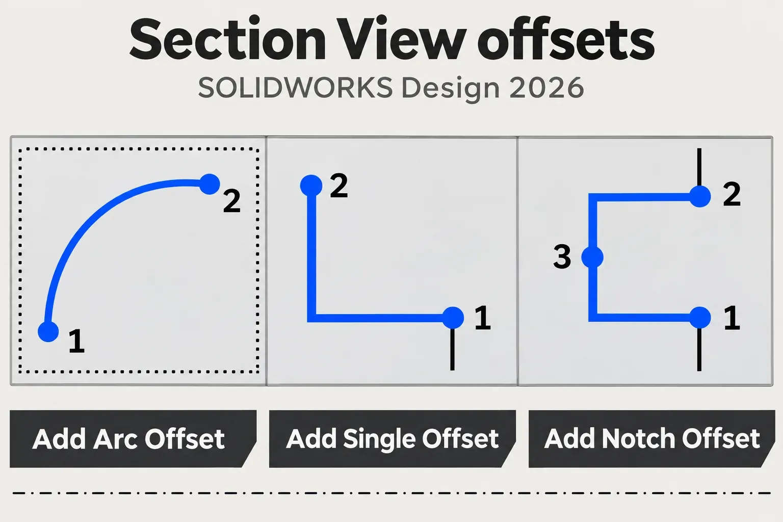
For an offset section, clear Auto-start section view before placing the initial cutting line. Use the Section View pop-up to add the offset. Add Single Offset takes two points; Add Arc Offset takes an initial point on the line and a second arc point; Add Notch Offset takes two points on the line for its width and a third for its depth. Accept the pop-up, then place the resulting view. Offsets can be combined.
For a custom sketched cut, create regular sketch segments and select them before clicking Section View. Construction segments are ignored. Use inferencing or sketch relations to attach the line to the model feature. A multiline cut must be sketched before starting the tool.
To add an offset to an existing section, right-click its line or view and choose Edit Cutting Line. Section View Assist becomes unavailable after direct edits to the line's sketch, so use the assisted route first when it can make the required cut.
If you only need to reveal a small area inside an existing view, a broken-out section uses a closed profile and specified depth. It modifies that view instead of placing a separate section beside it.
Set direction, label, scale and hatch
Select an existing section view to open its drawing Section View properties. Check these before adding dimensions:
- Direction. Double-click the cutting line or use Flip direction to reverse the cut. On a line with several segments, Flip Direction can also change the section's alignment.
- Label. Edit Label for the section letter, or double-click the letter on the sheet. Keep the parent-view letters consistent with the section label.
- Scale. Use parent scale follows the parent view's scale; Use sheet scale follows the sheet; Use custom scale sets a separate value for the section.
- Depth. For a single-segment cutting line, Section Depth limits the displayed distance behind the cut. It applies to components, not individual features. Slice section shows only the faces cut by the line.
The document's section-label settings control the drafting standard, letter appearance and scale display under Tools > Options > Document Properties > Views > Section. Follow the drawing standard required for the job.
Hatching belongs in solid material exposed by the cut; a hole remains clear. To change a local pattern, click the hatch and use Area Hatch/Fill. Material crosshatch uses the pattern, scale and angle specified by the part's material. Choose the correct assigned material before using its pattern as information on the drawing. Auto hatching alternates patterns between neighbouring assembly components or bodies in a multibody part.
Leave the intended components uncut
In an assembly drawing, Section Scope decides which components and rib features remain whole. For an existing section, right-click the view, choose Properties, then open Section Scope.
- Select components or rib features for Excluded components/rib features. Removing an item from that list lets the section cut it again.
- Select Don't cut all instances to leave every instance of a selected component uncut. Clear it to exclude only the picked instance.
- Use Exclude fasteners for Toolbox fasteners; structural members are excluded from that fastener rule. Show excluded fasteners previews the affected items.
A custom component can also carry the fastener designation: open it, choose File > Properties, then set IsFastener to 1 on the Custom tab. Use that property when the component should consistently be treated as a fastener; use the section's exclusion list for a choice specific to this view.
Section a part or assembly while modeling
A model Section View lets you inspect internal construction while leaving the model geometry intact. Its section state can survive saving and reopening the document. It doesn't apply to mesh bodies.
- With the part or assembly open, choose View > Display > Section View, or click Section View on the View toolbar.
- Choose Planar under Section Method for a cut defined by planes or planar faces.
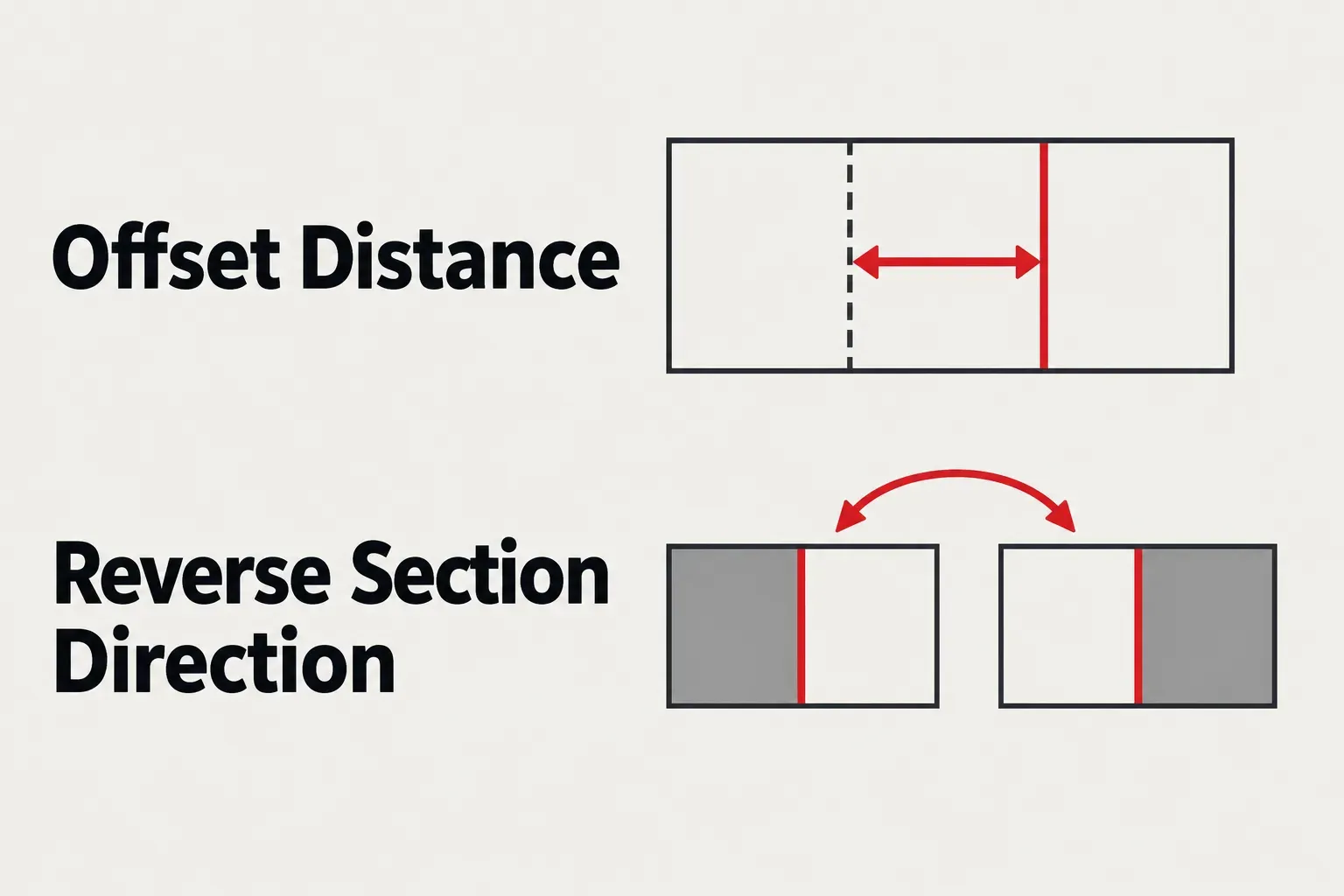
- Under Section 1, choose a reference plane or planar face. Set Offset Distance and the required rotation, then inspect which side is displayed. Reverse Section Direction flips the cut.
- Add Section 2 and then Section 3 only if the cut needs more planes. Section 3 becomes available after Section 2 is selected.
- If only certain bodies or components should be cut, use Include selected or Exclude selected under Section by Body or Component.
- Accept the view. Click Section View again to return to the full display. To adjust the cut, right-click the graphics area and choose Section View Properties.
For several cutaway regions, Zonal lets you choose intersection zones formed by the planes or faces and the model's bounding box. It doesn't support reversing the section direction. Use the zones themselves to select the areas to remove.
After rotating a plane, check Offset Method if the distance moves the cut in an unexpected direction. Reference plane measures normal to the oriented section plane; Selected plane measures normal to the plane selected in Section 1.
Graphics-only section gives faster display with limited selection: you can't select a sectioned face or edge. Leave it cleared when you need those entities for measurement. In a normal section, you can select cut edges or vertices to measure, but you can't start a sketch on a newly created section face.
Bring a saved model section into a drawing
The model PropertyManager's Save command offers two different destinations. View orientation recalls the section inside the model and isn't available in drawings. Drawing annotation view adds it to the drawing View Palette under Annotations.
For a single-plane part section, keep one Section active and clear Section by Body or Component and Transparently Section Bodies or Components to make Drawing annotation view available. The documented assembly condition is separate: one Section with Section by Component selected.
- In the model Section View PropertyManager, click Save.
- Choose Drawing annotation view, enter a view name and save it.
- Set the uncut components and hatching in Section Annotation View Props, then accept.
- In the drawing, open the View Palette, select or browse to the model, and drag the saved annotation view onto the sheet.
If Drawing annotation view is unavailable, check the one-Section and body/component conditions before changing the model. You don't need to add a physical cut feature just to expose the interior on the sheet.
Fix a section view that looks wrong
| Symptom | What to check |
|---|---|
| Wrong side or unexpected alignment | Reverse the cutting line with Flip direction. For a multi-segment line, inspect which segment sets the alignment. |
| Some areas stay uncut and appear olive | Check whether the line spans the model, whether the cut produces zero-thickness geometry, and whether Tools > Evaluate > Check identifies invalid model geometry. |
| Hatch pattern around the view boundary | The view is out of date. Right-click it and choose Update View; Edit > Update All Views updates the drawing's views. |
| No hatch inside a cut region | Click the region and check whether Area Hatch/Fill is set to None. If it uses Material crosshatch, inspect the part's material pattern. |
| Cutting line refuses to move | Inspect its sketch relations. A line attached to a hole centre follows the hole; removing that relation also removes that behaviour. |
For the olive, partly uncut result, extend a line that should span the whole model, or choose Partial section when the limited cut is intentional. Move a line that creates zero-thickness geometry; rebuilding the same cut doesn't remove that geometric condition.
If views repeatedly become stale, check Automatic view update on the drawing's top FeatureManager icon and Exclude from automatic update on the affected view. Updating when a drawing opens has its own setting: Tools > Options > System Options > Drawings > Performance > Allow auto-update when opening drawings.
Check that the cut follows the feature
Use a working copy for this check. Change the dimension locating the hole that the section line passes through, rebuild the part and save it. Update the drawing, then inspect the cutting line and the section together.
A line related to the hole's centre moves with that hole. The section should still expose the intended bore. If the line stays behind, inspect its relations or anchor it with a dimension in the parent view. Restore the intended hole position and check the result again before issuing the drawing.