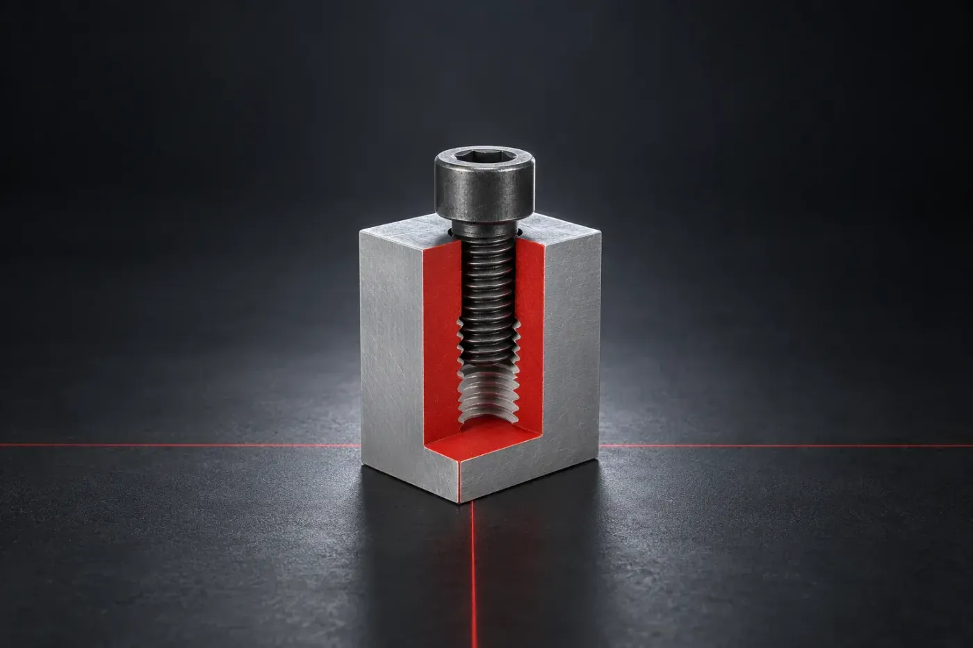
In SOLIDWORKS Design 2026, use Insert > Annotations > Cosmetic Thread on the starting circular edge when the thread needs a drawing callout. For a thread that needs helical faces in the model, use Insert > Features > Thread. I'd choose cosmetic threads for ordinary machined holes and stock fasteners because they keep the thread specification attached to the feature without building the helix. A thread that goes to a printer needs actual geometry.
Choose what the file must contain
A cosmetic thread stores thread attributes on an existing feature. It represents the minor diameter on a boss or the major diameter in a hole and can carry a drawing callout. The underlying solid still has a plain cylindrical surface. A modeled thread adds a swept cut or boss, so its grooves or ridges become part of the solid.
| Deliverable | Choose | What to check |
|---|---|---|
| A drawing for a tapped hole or threaded shaft | Cosmetic Thread, or a Hole Wizard tapped hole with a cosmetic thread | Standard, size, depth and drawing callout. |
| An ordinary assembly using stock screws | Cosmetic threads unless the helical shape is required | Matching specifications, alignment and interference results. |
| A close view whose silhouette must show the thread | Modeled Thread | Profile, pitch, handedness and end treatment. |
| A printed part with working thread surfaces | Modeled Thread with a profile adapted to the job | Mating geometry and the printer/material process. |
Cosmetic threads avoid the extra helical faces that a modeled feature creates. Keep that lighter representation for routine assemblies and drawings; add the geometry when the deliverable needs its shape.

Add a cosmetic thread to a shaft or hole
Start with the cylindrical boss or hole already present. Cosmetic threads work on internal and external features; you don't need a modeled helix to identify a tapped hole.

- Select the circular edge where the thread starts. On a cylindrical shaft or hole, this is the rim of the threaded region.
- Click Insert > Annotations > Cosmetic Thread, or use Cosmetic Thread on the Annotation toolbar.
- Under Thread Settings, choose Standard, Type and Size. The Size list contains valid values for the selected edge.
- Set End Condition: Blind for a specified depth, Through through the existing geometry, or Up to Next to the next intercepting entity. Enter Depth for Blind.
- Check the thread callout and confirm the feature. When a standard drives the callout, its text cannot be edited directly in this PropertyManager.
The edge-selection rule changes for conical features: select the major diameter of a conical hole or the minor diameter of a conical boss. The Cosmetic Threads PropertyManager then exposes the applicable diameter or conical offset.
If you want shaded thread markings on the model, open Tools > Options > Document Properties > Detailing and select Shaded cosmetic threads under Display filter. This changes the display; it doesn't cut grooves into the solid. Also check that the parent feature or component is visible, because cosmetic-thread visibility follows its parent.
Use Hole Wizard for a new tapped hole
For a new standard tapped hole, I'd start with Hole Wizard because the hole type, size and annotation stay in one feature. Select a face, click Insert > Features > Hole Wizard, choose Straight Tap or Tapered Tap, then set the standard, type, size and end condition. Use the Positions tab to locate the hole.
In the Hole Wizard thread options, Cosmetic thread cuts the bore at the tap-drill diameter and adds the thread representation. With thread callout adds its drawing annotation. Neither option creates helical faces. For a blind tapped hole, the tap thread depth cannot exceed the blind hole depth.
Show the thread on the drawing
Cosmetic threads from part documents enter drawing views automatically. Callout behavior follows the drawing standard: ANSI drawings insert thread callouts automatically; ISO, JIS and other standards don't use that same automatic callout behavior. If a defined callout is missing, right-click the cosmetic thread in the drawing and choose Insert Callout.
Assembly drawings need an import check. Use Insert > Model Items and select Cosmetic thread, or enable Cosmetic Threads - assembly (may affect performance) under Tools > Options > Document Properties > Detailing > Auto insert on view creation. In the Drawing View PropertyManager, check Import annotations and Cosmetic threads under Import options. These are the documented assembly-to-drawing import controls.
For a Hole Wizard hole, use Insert > Annotations > Hole Callout, select the hole edge and place the note. The Hole Callout reads the hole information, including additional Hole Wizard data. Keep its size and type variables instead of replacing the whole note with typed text.
Model an external thread with the Thread feature
Start with a cylindrical shaft whose diameter comes from the intended thread design. SOLIDWORKS states that Thread does not autosize to the model. Selecting a shaft edge does not select a compatible thread size for you.
- Select the starting circular edge and click Insert > Features > Thread.
- Under Thread Location, check Edge of Cylinder. Set a start offset only if the thread must begin away from that edge; check its direction in the preview.
- Under Specification, select the intended Type and Size. For the documented external cut-thread example, SOLIDWORKS uses Metric Die and M6x1.0; those are example selections, not values for every shaft.
- Select Cut Thread to remove material with the profile, or Extrude Thread to add it. Inspect how the profile meets the shaft before accepting the method.
- Set End Condition. Use Blind and Depth for a length, Revolutions for a turn count, or Up to Selection for a plane or planar face perpendicular to the thread axis. Check the start and end of the preview.
- Choose Right-hand thread or Left-hand thread under Thread Options. Inspect the complete preview and confirm.

The cut-thread example establishes the command and an example profile. Your shaft diameter, profile and thread length still have to agree. If you use Trim with start face or Trim with end face, the profile must extend beyond the trimming face.
The built-in Type and Size profiles are nominal profiles that need modification for production-quality threads. Check the specified thread form, dimensions and tolerances before sending modeled geometry for fabrication.
For an internal modeled thread, check the bore and profile together
Prepare the intended cylindrical bore, select its starting inner circular edge and open the same Thread command. Choose the profile and size for the internal thread, then inspect their position against the bore wall with Locate Profile. Set the thread method, end condition and handedness as above.
Cut Thread works when the selected profile removes the required material from that bore. Another profile and starting bore may require Extrude Thread to add the helical ridge. The thread guidelines explicitly warn that a cut profile which works on a shaft may require extrusion on a hole. There is no reliable rule that every internal thread must use Cut Thread.

If the feature fails after changing an offset, restore the previous offset and try a smaller change. A profile displaced away from the underlying body can lose contact. Check diameter and pitch overrides too; a profile name alone doesn't establish the final thread geometry.
Check the joint before treating it as a fit
For an assembly, open Tools > Evaluate > Interference Detection and select the components. Resolve the components for an accurate check: Large Design Review uses approximate calculations and omits some options.
Enable Create matching cosmetic threads folder, then click Calculate to separate interferences between components with properly matched cosmetic threads. Mismatched or misaligned threads and other interfering geometry remain in the ordinary results. Create fasteners folder is a separate grouping option; neither folder is a blanket instruction to ignore every screw-related clash. These distinctions are defined in the Interference Detection options.
For a printed joint, inspect actual helical faces and the mating part, then check a sample made with the intended printer, material and settings. Cosmetic markings cannot supply missing geometry to the exported mesh. Choose any fit allowance for that process rather than copying an unexplained clearance.
Change the design and follow the reference
Change one driving dimension deliberately, then rebuild. For a cosmetic thread, inspect the selected edge, thread size and depth, and reopen the drawing to check the callout. For a Hole Wizard tapped hole, changing Size updates its calculated depths only while Automatically Calculate Depth remains selected.
For a modeled thread, changing the shaft or bore diameter does not make Thread choose a new profile. Recheck Type, Size, any diameter or pitch overrides, the starting edge and the end condition. Inspect both ends and the mating component again. Continue with the appropriate part-feature workflow only after the geometry and the drawing describe the same intended thread.