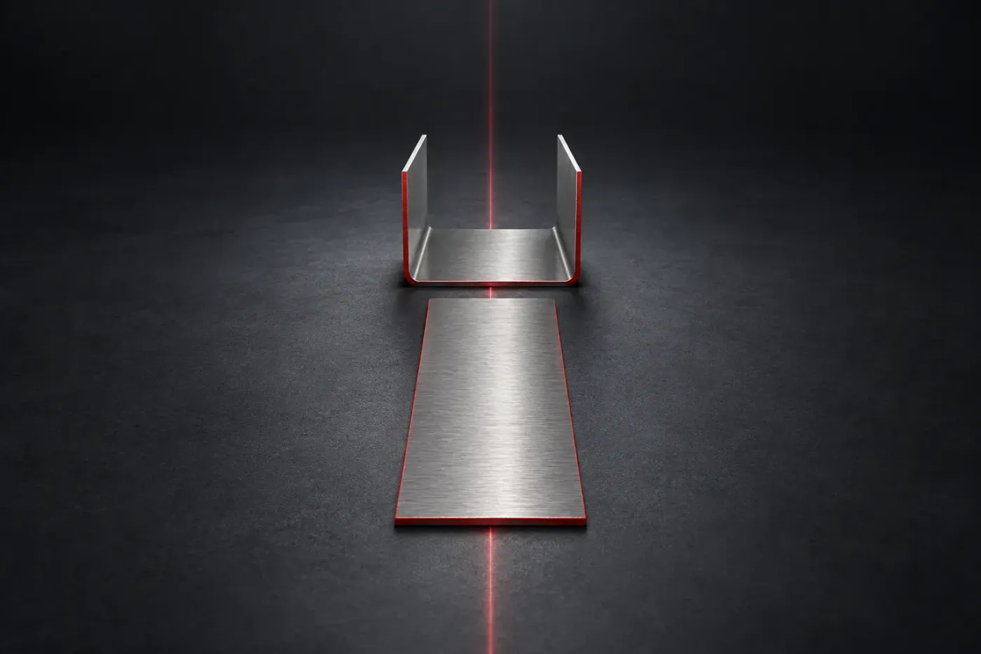
Build a SOLIDWORKS 2026 sheet metal part with Base Flange/Tab, set its thickness and bend parameters, then add flanges or sketched bends. Use Flatten to inspect the complete blank and Export to DXF/DWG from the Flat-Pattern feature to prepare the cutting file. The blank's size depends on the bend data, so use the radius and allowance method supplied by the shop that will bend it.
I'd start a new bracket with sheet metal features because its thickness and default bend settings stay together in the model. Converting a solid is useful when that solid already exists, but it adds another set of faces, bends and rips to check.
Choose the starting shape
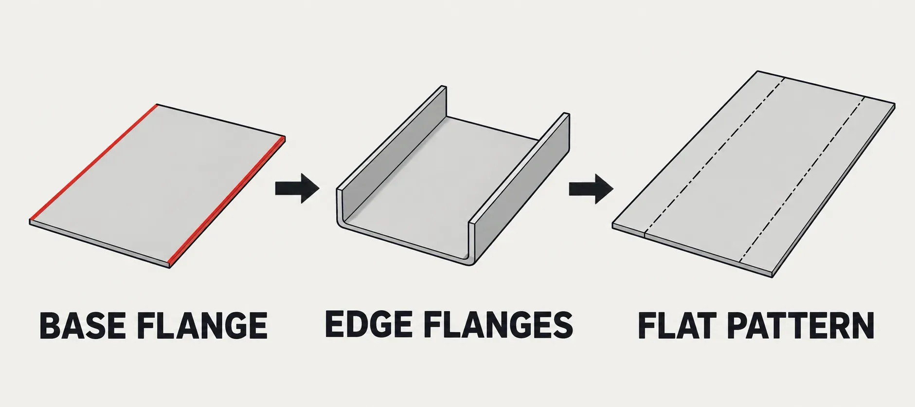
For a simple channel, start with a rectangular base and add two upright flanges. The rectangle sets the base footprint; it is not the final blank length, because the edge flanges add material.
| What you have | Starting route | What controls the result |
|---|---|---|
| A new bent part | Base Flange/Tab, then Edge Flange | The base sketch, flange dimensions and sheet metal parameters. |
| A blank whose flat size is already fixed | Base Flange/Tab, then Sketched Bend | The existing blank outline and dimensioned bend lines. |
| An existing solid or imported sheet-shaped body | Convert to Sheet Metal | The existing geometry and its sheet metal conversion feature. |
SOLIDWORKS recommends sheet metal features as the first design method; Insert Bends and Convert to Sheet Metal are alternatives. Keep conversion as a separate workflow rather than trying to reproduce a flange tutorial on an arbitrary solid.
Create the base flange
Get the intended stock thickness, inside bend radius and bend allowance method before entering values. A K-factor, bend allowance, bend deduction or table describes how the blank accounts for the bend. Those inputs need to match the material, thickness and tooling used for the job.
- Start a part, choose a sketch plane and draw a closed rectangle. Dimension its base footprint and position it relative to the origin.
- Select the sketch and click Base Flange/Tab on the Sheet Metal toolbar, or Insert > Sheet Metal > Base Flange.
- Set Thickness and Bend Radius, or select the approved gauge table. Check the preview to see which side of the sketch receives the thickness; use Reverse direction or Symmetric when required.
- Under Bend Allowance, choose the method supplied for the job. Enter its value, or select the applicable bend table.
- Set Auto Relief. For Rectangular or Obround relief, choose a relief ratio or specify Relief Width and Relief Depth. Confirm the feature.
For a single closed profile, Direction 1 and Direction 2 are absent. Do not look for an extrusion depth to turn this rectangle into a sheet: Thickness supplies its thickness. An open-profile base flange uses a different set of controls.
The base flange parameters also support material-linked sheet metal settings. If those settings or a gauge table drive the part, check that source before trying to replace a controlled value manually. Assigning a physical material and choosing fabrication parameters are separate decisions; a custom material can link sheet metal parameters when that link has been configured.
Keep the defaults in the sheet metal feature
The FeatureManager tree gains the sheet metal features and a suppressed Flat-Pattern feature. Edit Sheet-Metal1 to inspect the part's default bend radius, allowance and relief. Later features can inherit these values or override them.
I'd leave Use default radius selected on ordinary flanges so a deliberate default change reaches them together. Use a local override only when that bend requires a different value, and keep that exception visible in the drawing or manufacturing instructions.
If the Sheet Metal tab is hidden, the Insert menu routes still provide access to the commands. To show the tab, right-click a CommandManager tab and select Tabs > Sheet Metal.
Add an edge flange without losing the drawing dimension
- Keep the model folded. Click Edge Flange, or Insert > Sheet Metal > Edge Flange.
- Select one straight edge of the base. The new flange's thickness follows the sheet metal part.
- Set Flange Angle.
- Under Flange Length, choose Blind and enter the required length. Choose the measurement origin that matches the drawing, such as Outer Virtual Sharp or Inner Virtual Sharp.
- Under Flange Position, choose the appropriate Bend Position. Inspect the preview against the base edge and the drawing's inside or outside dimensions.
- Leave Use default radius selected unless this is an intentional exception. Check relief at the flange ends, then confirm. Add the opposite flange in the same way.
The flange length origin and bend position are separate controls. A virtual sharp is the theoretical intersection of the straight faces extended through the bend; it is not a point on the curved surface. If the flange is displaced by a sheet thickness or its measured height differs from the intended dimension, revisit these controls before changing the sketch to compensate.
Relief is a local cut where the bend needs it. A flange that stops partway along an edge may need relief at its end. Use the feature's Custom Relief Type for a local exception; change the sheet metal default when the requirement applies throughout the part. Avoid treating a relief notch as an accidental hole to fill.
Use a sketched bend when the blank size must stay fixed
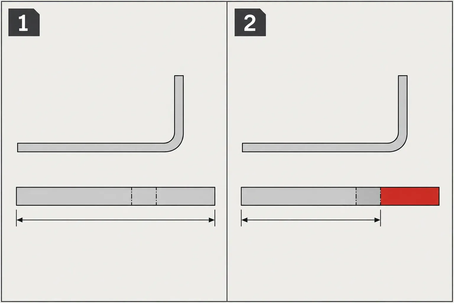
A sketched bend folds existing sheet along a sketch line; an edge flange creates a flange from a selected edge. This distinction matters when you already have a fixed-size strip or cutting outline. The documented comparison preserves the sketched blank's flat length, while the edge-flange route derives the blank length from its dimensions and bend allowance.
Sketch and dimension a line on a planar face of the folded sheet metal part, then select Sketched Bend or Insert > Sheet Metal > Sketched Bend. Choose the Fixed Face, bend position, angle and radius. Check which portion stays still before confirming. Sketched bends use line entities on flat faces of the folded part; the tool does not work on the fully flattened state. The line does not have to span the whole face.
Flatten the complete part
Click Flatten on the Sheet Metal toolbar, or unsuppress Flat-Pattern1. Inspect the perimeter, holes, bend regions and corner reliefs. If geometry intersects itself and prevents flattening, SOLIDWORKS warns and highlights the feature responsible; inspect that feature's extent, position and relief.
Keep Flat-Pattern at the end of the feature history. A feature added while it is unsuppressed goes below it and exists only in the flat. Return to the folded state before adding another flange or feature intended for the finished folded part.
Unfold is for temporarily opening selected bends, for example to place a cut across one before folding it back. It is not the same output as the complete flat pattern: corner treatments apply in the flat pattern and can make it differ from an unfolded part. Use the complete Flat-Pattern result for the final blank check.
Export the flat pattern to DXF
You can export a flat-pattern DXF while the model remains folded. Start from the Flat-Pattern feature so the export targets sheet metal rather than only a selected planar face.
- Right-click Flat-Pattern in the FeatureManager tree and choose Export to DXF/DWG. Choose the file destination and name.
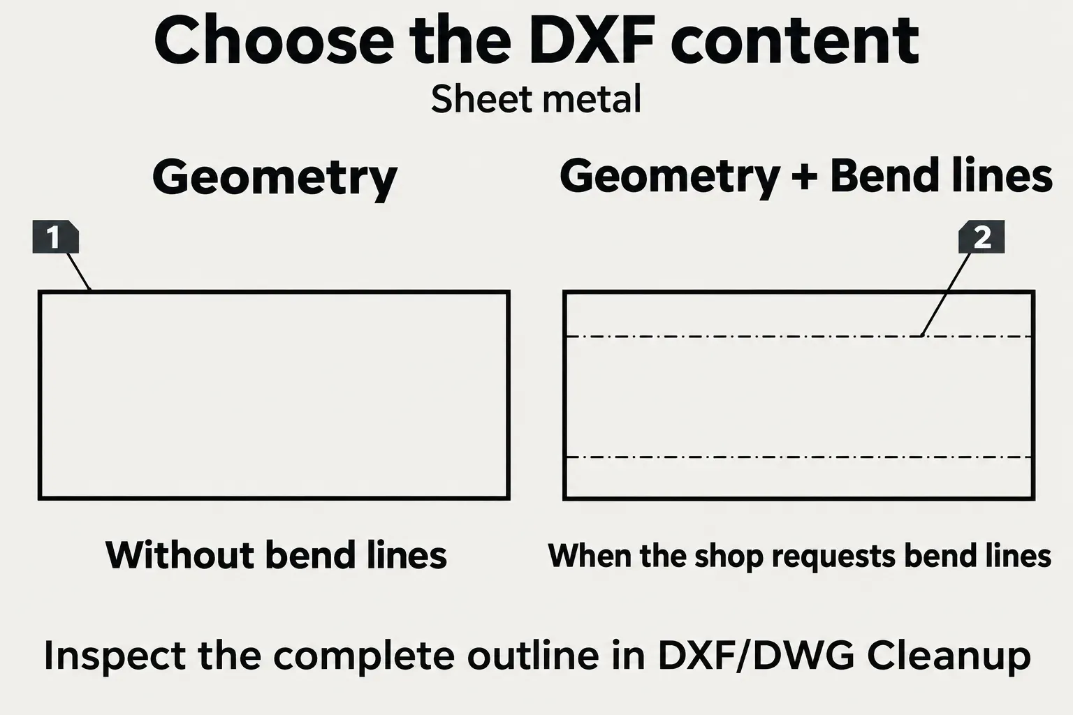
- In the DXF/DWG Output PropertyManager, verify that the export type is Sheet metal. Keep Geometry selected.
- Include Bend lines only when the receiving shop wants them. Clear it to omit bend lines.
- Set Output Alignment if required: choose an origin vertex and orthogonal edges for the X and Y axes, or leave the origin blank to use the model origin.
- Confirm to open the DXF/DWG Cleanup preview. Inspect the complete outline and cut-outs, check the bend lines if included, remove unwanted entities and click Save.
The export context controls whether Sheet metal, planar faces or named views are exported. A face export can look plausible while omitting the flanges, so verify the whole developed outline in the preview.
For the File-menu route, use File > Export As when SOLIDWORKS Design was installed from the 3DEXPERIENCE platform; otherwise use File > Save As and select DXF. If the Design with SOLIDWORKS add-in opens a Save As New dialog, choose Save to This PC.
Confirm the delivery requirements with the shop: material and thickness, radius and bend data, whether bend lines belong in the DXF, and whether it also wants the folded model or a dimensioned drawing. For example, SendCutSend fixes inside bend radius and K-factor for each material thickness it bends. That is its ordering process; use the actual fabricator's data for another job.
Change the thickness and inspect the blank again
In a copy of the part, choose another approved thickness or gauge in the sheet metal feature, then rebuild. Check that the base and flanges share that thickness. Inspect the default radius and any local flange overrides, then flatten again: the bend calculation and blank must reflect the new inputs.
For the edge-flange channel, check the inside or outside dimensions used on the drawing and the revised developed outline. A blank folded with sketched bends retains its sketched flat length; inspect its folded dimensions instead. If a bend keeps an unexpected radius or allowance, inspect Use default radius, the gauge-table setting and Custom Bend Allowance on that feature. Use K-factor and bend allowance calculations when you need to reconcile the blank with the shop's bend data.